
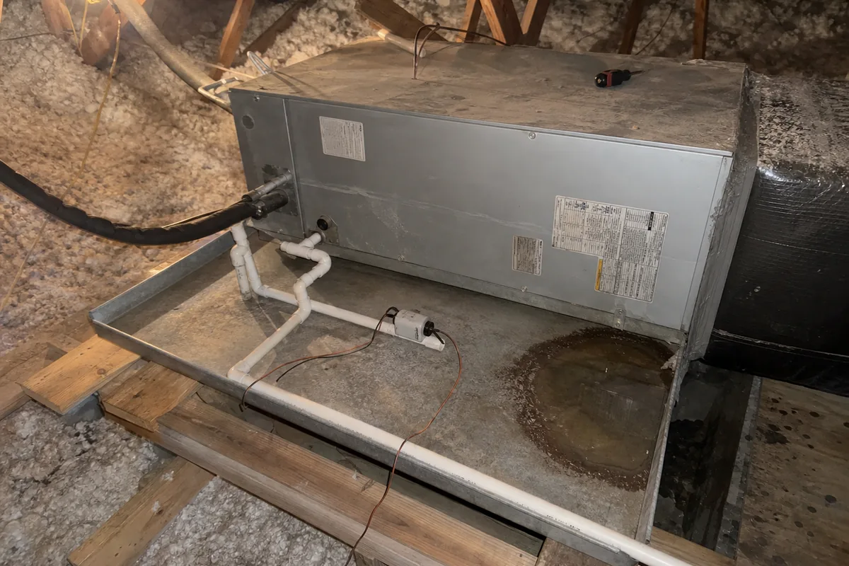
Code requires secondary condensate protection when overflow from the equipment drain pan or a blockage in the condensate drain could damage building components, and compliance can include a separate overflow drain, an auxiliary pan and drain, or an approved water level detection arrangement that shuts off the equipment.
That answer is simple. Applying it consistently is where shops get into trouble.
An air handler in an attic, above a finished ceiling, or near materials vulnerable to water creates a different risk from equipment installed where condensate can escape without damaging the building. A stopped primary drain in the wrong location can become a drywall, insulation, flooring, or contents problem before anyone notices that cooling has stopped.
For a contractor, secondary protection therefore belongs in the same conversation as equipment placement, drainage, commissioning, and job documentation. It is not merely an accessory decision made at the end of an installation.
Why this failure is different from a no-cool call
Most HVAC failures announce themselves through comfort. The system stops heating or cooling, the occupant notices, and the shop receives a service call.
A condensate failure can continue quietly while water leaves the intended drainage path. The occupant may first see a ceiling stain, wet insulation, damaged trim, or water near the equipment. By that point, the conversation is no longer limited to restoring operation.
Location changes the consequence. A restricted drain at equipment installed over a suitable unfinished area may create a maintenance problem. The same restriction above finished space can create property damage. That distinction is why the code requirement focuses on whether overflow or drain stoppage would damage building components.
The practical question during a survey is not simply, “Does this coil make condensate?” It is, “What gets wet if the primary drainage system stops working?”
The language a caller uses on the phone tracks that same distinction before anyone drives out. “Water is coming through the ceiling” is a different dispatch than “the little light on the unit is blinking,” even though both can trace back to the same blocked primary drain. One is active damage in progress. The other might be a switch doing exactly what it was installed to do.
That question should be answered before the equipment is set. It affects the selected protection method, drain routing, switch location, service access, and the photographs a technician should capture before leaving.
Secondary protection also deserves functional verification. The presence of a pan, pipe, or switch does not prove that the installation will respond correctly to rising water. A pan can be poorly positioned. A drain can terminate where no one will notice it. A switch can be installed at the wrong elevation or wired without actually interrupting equipment operation.
What the codes actually require
The International Residential Code and the International Mechanical Code, both published by the International Code Council, require secondary protection where overflow from a cooling or evaporator coil drain pan, or stoppage in its condensate drain piping, would damage building components.
The enforceable requirement is the code edition the local jurisdiction has actually adopted. Editions differ, local amendments may apply, and section numbers move. Verify the requirement in the adopted code instead of trusting a section number quoted in an article. This is the same discipline contractors should apply when distinguishing standards versus the code your jurisdiction adopted.
The IRC and the IMC recognize several common compliance paths:
- An auxiliary drain pan with a separate drain that discharges at a conspicuous point of disposal.
- A separate overflow drain line connected to the coil drain pan and routed to a conspicuous point.
- An auxiliary drain pan without a separate drain, combined with a water level detection device.
- A water level detection device arranged to shut off the equipment served when the primary drain is blocked.
These are distinct arrangements. Parts from different methods should not be combined casually while assuming the result meets the intent of any one method.
A conspicuous discharge gives the occupant or service technician a visible warning that the primary drainage system needs attention. A shutoff device takes a different approach by stopping operation before continued condensate production causes overflow. An auxiliary pan provides containment, but its placement and associated drain or detection device determine whether it forms a complete protection method.
The code text expects a water level detection device to shut off the equipment served when the primary drain becomes blocked. It also references conformance to UL 508 for these devices. A switch that changes state but does not stop the served equipment has not completed that function.
These codes also subject condensate drain piping to sizing and slope requirements. The commonly expressed minimum is 3/4 inch nominal pipe size with a slope of not less than 1 percent in the direction of discharge. Secondary protection cannot compensate for a primary drain that was installed without adequate pitch or with a route that encourages retention and blockage.
The code text further requires appliances, equipment, or insulation that could be damaged by a filled auxiliary pan to be installed above the rim of that pan. A pan cannot provide useful containment if vulnerable material sits in the water before the protection method responds.
For down-flow units and other coils that have no secondary drain and no provision for a secondary or auxiliary pan, the code text calls for a water level monitoring device inside the primary drain pan. Equipment configuration does not eliminate the need to address overflow risk.
Where installs go wrong
A frequent problem is treating the auxiliary pan as a complete solution merely because it is present. A pan without the drain or detection arrangement required for the chosen compliance path is just a container. If its capacity is eventually exceeded, the building is still exposed.
Pan geometry matters as well. The pan must be positioned to receive water from the equipment it protects. Equipment supports, insulation, wiring, and nearby components should not defeat containment or sit where accumulated water will damage them.
Drain routing creates another set of failures. A secondary line may have poor slope, an unsupported sag, or a termination that is neither conspicuous nor readily associated with the affected system. If water can discharge for an extended period without anyone seeing it, the warning function has been weakened.
Primary and secondary drainage paths should remain meaningfully independent. Routing choices that allow the same restriction to disable both paths undermine the purpose of secondary protection.
Detection devices introduce electrical and functional questions. The device must respond at the intended water level, and its control arrangement must stop the equipment served. Technicians should not assume that wire placement proves operation. A functional test should confirm the actual response.
Serviceability is another common blind spot. A switch or cleanout placed where a technician cannot reach it is less likely to be inspected and tested. An attic installation may technically include every expected component while making routine drain maintenance unnecessarily difficult.
Documentation can also fail. A wide photograph showing an air handler does not necessarily show pan coverage, drain separation, switch placement, or termination. As with recorded combustion readings, useful records capture the condition that was verified, not merely the presence of equipment.
What a shop should standardize
Start with a survey question that forces the consequence into view: would condensate overflow or a stopped drain damage any building component? Record the answer and the protection method selected for the location.
Create installation details for the arrangements your crews commonly use. Each detail should show the intended primary drain route, secondary method, pan relationship, detection point, equipment shutoff connection, supports, and access for maintenance. The detail should also leave room for jurisdiction-specific requirements.
Add drain pitch and protection checks to commissioning. Confirm that piping falls toward discharge, that vulnerable equipment and insulation remain above the auxiliary pan rim, and that the secondary discharge terminates where it can be noticed when that method is used.
Where a water level detection device is the selected method, test the complete control result. The meaningful outcome is that the served equipment shuts off under the simulated blocked-drain condition. Record that result with the device location and wiring condition.
Photographs should establish context and detail. Capture equipment placement within the auxiliary pan, the primary and secondary connections, the detection device, accessible cleanout points, and the termination of any separate drain. The record should make the chosen compliance path understandable to someone who was not present.
Service procedures should preserve the original protection strategy. After drain cleaning, equipment replacement, or control work, verify that the switch remains correctly positioned and capable of stopping operation. Check that pans have not shifted and that drainage routes remain supported and open.
Finally, give estimators, installers, service technicians, and quality reviewers the same vocabulary. A note saying “add float switch” is less useful than identifying the intended protection method and the response that must be verified. Clear scope reduces field guesswork and makes final review more consistent.
Condensate overflow protection is a small part of an HVAC installation with an unusually direct connection to building damage. Treating it as a designed, tested, and documented system gives the shop a repeatable way to protect the property and demonstrate installation quality.
That distinction is also exactly what Dial 72’s emergency escalation is built to catch on the first ring. A caller describing active water intrusion gets routed differently than a caller reporting an alarm or a switch trip with no visible water yet, so a shop is not booking a slow drip into the same urgent slot as a ceiling that is actively staining.
Quick answers
When is secondary condensate protection required? The International Residential Code and International Mechanical Code require it where pan overflow or a stopped condensate drain would damage building components, subject to the edition and amendments adopted locally.
What counts as an acceptable method? The IRC and the IMC recognize a separate overflow drain, an auxiliary pan with a separate conspicuous drain, an auxiliary pan with water level detection, or a detection device that shuts off the equipment.
What does a water level detection device have to do? It must shut off the equipment served when blockage of the primary drain causes the water level to rise.
What pipe size and slope are expected? The commonly expressed code minimum is 3/4 inch nominal pipe size and a slope of not less than 1 percent toward discharge.
Is a float switch alone enough? Only when its installation forms an accepted protection method, conforms to the applicable requirements, and actually shuts off the served equipment at the intended water level.
